How to Determine the Optic Axis of a Crystal
Practical methods for laboratory inspection, crystal orientation, and optical manufacturing
Determining the optic axis is a prerequisite for manufacturing birefringent and nonlinear optical components. The appropriate method depends on the crystal type, sample condition, transparency, and angular tolerance. This guide compares six practical approaches used in laboratory inspection, blank orientation, and production verification.
1. Fundamentals
Birefringent crystals are divided into uniaxial and biaxial crystals. Uniaxial crystals—including calcite, YVO₄, α‑quartz, and BBO—have one optic axis. BBO is a negative uniaxial crystal. For propagation along the optic axis, the ordinary and extraordinary waves have the same phase velocity, so birefringent splitting is not observed in that direction.
Biaxial crystals—including LBO, KTP, and mica—have two optic axes and require a more complex orientation analysis. Optic‑axis orientation is a critical upstream step: angular error can reduce polarization extinction ratio, shift phase‑matching conditions, or prevent a finished component from meeting its specification.
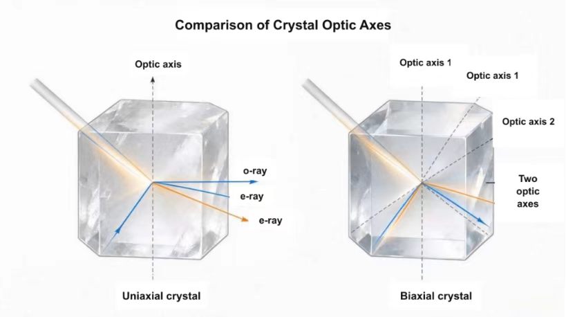
Figure 1. A uniaxial crystal has one optic axis; a biaxial crystal has two. BBO is negative uniaxial, whereas LBO is biaxial.
2. Method 1 — Visual Black Dot Test for Natural Calcite
This quick method uses the strong birefringence of transparent calcite and is suitable for rough identification of a natural crystal or an uncoated blank.
- Place the calcite sample over a small black dot or a fine printed line.
- View the mark through different faces while slowly rotating or tilting the crystal.
- In most directions, two images are visible because the incident light separates into an ordinary ray (o‑ray) and an extraordinary ray (e‑ray).
- When the viewing direction approaches the optic axis, the two images overlap and the apparent doubling disappears.
Limitations: This method is qualitative and is affected by surface quality, inclusions, crystal shape, and viewing geometry. It is not a substitute for precision orientation.
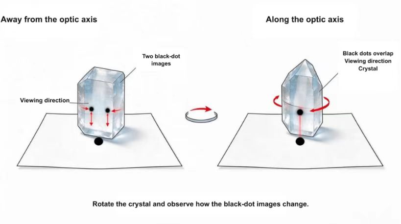
Figure 2. In a simple calcite black‑dot test, image doubling is visible off‑axis and disappears when viewed along the optic axis.
3. Method 2 — Conoscopic Observation with Crossed Polarizers
A polarizing microscope equipped for convergent‑light observation provides a classical and reliable way to locate an optic‑axis direction and distinguish uniaxial from biaxial behavior.
Equipment:
- Polarizing microscope
- Crossed polarizer and analyzer
- Condenser for convergent illumination
- A suitable crystal section or transparent sample
Procedure:
- Place the sample between the crossed polarizer and analyzer.
- Use convergent illumination and focus the conoscopic interference figure.
- Rotate and tilt the sample until the interference figure is centered and symmetric.
- Interpret the isogyres and interference rings to identify whether the crystal is uniaxial or biaxial and to estimate the optic‑axis direction.
A centered dark cross is characteristic of a uniaxial crystal observed along its optic axis under ideal conditions. A biaxial interference figure contains two melatopes and changes in a different way as the stage is rotated.
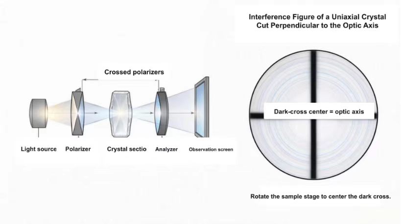
Figure 3. Simplified conoscopic arrangement with crossed polarizers. The observed interference figure is used to determine crystal type and optic‑axis orientation.
4. Method 3 — Laser Birefringence Scanning
A collimated laser can be used for a fast orientation check on transparent blanks. The sample is mounted on a rotation or tilt stage, and the transmitted spot pattern is monitored on a screen or camera.
- Direct a narrow, collimated beam through the crystal and observe the transmitted spot or polarization state.
- Rotate or tilt the sample in controlled increments.
- For a uniaxial crystal, search for the direction in which birefringent angular separation is minimized or disappears.
- Repeat the scan from more than one face to reduce ambiguity and record the stage angles.
This method is useful for preliminary orientation of calcite, YVO₄, quartz, and other transparent uniaxial blanks. Surface wedge, internal stress, beam divergence, and refraction at the entrance and exit faces can affect the result. For LBO, which is biaxial, a simple single‑axis search is not sufficient for final orientation; optical calculations and crystallographic verification should be used.
5. Method 4 — Optical Rotation Measurement for α‑Quartz
α‑Quartz is optically active. When linearly polarized light propagates along its crystallographic c‑axis, the plane of polarization rotates. Measuring this rotation at a known wavelength and thickness can therefore help verify whether a quartz sample is oriented near the optic axis and can also distinguish left‑handed from right‑handed quartz.
This method is specific to optically active materials and should not be generalized to calcite, BBO, LBO, or other crystals without confirming the applicable optical behavior.
6. Method 5 — X‑Ray Diffraction Orientation
X‑ray diffraction (XRD) determines crystallographic planes and axes from diffraction peaks. The measured crystallographic orientation can then be converted into the required optic‑axis or phase‑matching geometry using the known crystal structure and optical data.
- Suitable for production blanks, coated components, and tight cutting tolerances
- Provides high angular precision and traceable orientation data
- Especially important for biaxial crystals and nonlinear crystals with specified phase‑matching cuts
- Requires calibrated equipment, correct indexing, and experienced interpretation
7. Method 6 — Reference Data and Theoretical Calculation
For standard crystal species, crystallographic references and refractive‑index data provide the starting point for orientation design.
- In calcite, YVO₄, α‑quartz, and BBO, the optic axis is parallel to the crystallographic c‑axis. BBO is a negative uniaxial crystal.
- LBO and KTP are biaxial crystals. Their two optic‑axis directions depend on the three principal refractive indices and vary with wavelength.
- For nonlinear‑optical components, the required phase‑matching direction is not automatically the same as an optic axis. Use validated Sellmeier equations and the specified wavelength, interaction type, and temperature.
- Published data guide the nominal cut, but the actual blank should still be verified experimentally before precision processing.
8. Practical Method Selection
| Sample / Objective | Recommended Method | Use Note |
| Natural calcite; rough identification | Visual black‑dot test | Fast, qualitative check |
| Laboratory thin section | Conoscopic polarizing microscopy | Crystal type and optic‑axis direction |
| Transparent uniaxial blank; preliminary orientation | Laser birefringence scan | Fast scan before precision verification |
| Quartz handedness or c‑axis verification | Optical rotation measurement | Use a known wavelength and thickness |
| Coated, biaxial, or phase‑matched components | XRD plus optical calculation | Preferred for tight angular tolerances |
Conclusion
For rough identification, visual, polarizing‑microscope, and laser methods are efficient. For final cutting of high‑precision, coated, biaxial, or phase‑matched components, crystallographic orientation and documented optical calculations should control the process. Combining methods reduces ambiguity and improves manufacturing reliability.
For special requirements in different application scenarios, Fuzhou Chenxin Optoelectronics Co., Ltd. can provide relevant standard series products or special custom‑made services.
Cooperation Inquiry