What Should Be Tested for High‑Power Laser Crystals and Optical Components?
A practical inspection framework covering materials, fabrication, coatings, and high‑power operating conditions
There is no universal set of inspection limits for high‑power laser crystals and optical components independent of their operating conditions. The inspection plan and acceptance limits should be defined according to wavelength, continuous‑wave or pulsed operation, pulse duration, repetition rate, beam size, power or energy density, polarization, angle of incidence, cooling conditions, and component architecture.
This article outlines common inspection items for high‑power laser crystals, coated optics, and assembled optical modules. In an actual project, development verification, lot qualification, and production inspection should be distinguished, with final acceptance based on the customer specification and mutually agreed test conditions.
Inspection Overview
| Category | Typical Parameters | Key Point |
| Bulk material | Internal defects, homogeneity, stress, absorption, orientation | Determines wavefront quality, thermal stability, and long‑term reliability |
| Surface fabrication | Surface imperfections, roughness, figure, angles, edge chips | Limits should reflect wavelength, beam size, and power density |
| Optical coatings | Spectral response, absorption, uniformity, durability, LIDT | Low reflectance does not necessarily mean low absorption |
| Functional performance | Extinction ratio, phase matching, conversion efficiency, gain parameters | Use separate criteria for polarizing, nonlinear, and gain crystals |
| Operating‑condition validation | Thermal distortion, depolarization, irradiation aging, thermal cycling | Simulate the actual power, cooling, and environment |
| Assembly and delivery | Mounting stress, sealing, coaxiality, stray light | Distinguish 100% inspection from sample‑based qualification |
1 Define the Actual Laser Operating Conditions First
Before specifying inspection limits, the actual application conditions must be established. Even for the same material, absorption, thermal behavior, and laser‑damage risk can change significantly with wavelength, pulse duration, beam size, or cooling method.
- Laser wavelength and spectral range, including harmonics or unwanted spectral bands;
- CW or pulsed operation, including pulse duration, repetition rate, and duty cycle;
- Beam size, spatial profile, peak power, and energy or power density;
- Angle of incidence, polarization, clear aperture, and whether the beam approaches the component edge;
- Operating temperature, cooling method, mounting configuration, and expected service life.
2 Bulk Crystal and Substrate Quality
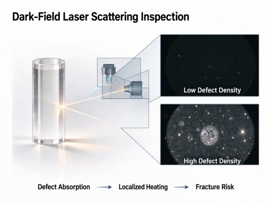
1. Inclusions, bubbles, and scattering sites. Dark‑field illumination or laser‑scattering inspection can be used to observe and quantify defects. Absorbing defects may produce localized heating, while scattering defects can degrade beam quality. Their effect depends on defect type, location, and the actual laser conditions.
2. Refractive‑index homogeneity. Specify either the peak‑to‑valley Δn or the refractive‑index gradient, together with test wavelength, sample thickness, clear aperture, and whether low‑order terms such as tilt and defocus have been removed. A value such as “Δn < 1 × 10⁻⁶/cm” should not be treated as a universal requirement for every material and size.
3. Stress birefringence. A polariscope or interferometric method may be used. Residual stress can introduce wavefront error, thermally induced birefringence, and reduced polarization performance, and may increase cracking risk during assembly or thermal cycling.
4. Impurities and residual absorption. Measure the absorption spectrum or absorption coefficient at the relevant wavelength. In high‑power applications, even small absorption can produce heating, thermal lensing, or thermal depolarization.
5. Crystal orientation. X‑ray diffraction or another suitable method can verify the optical axis, cut direction, or phase‑matching angle. The allowable error should be derived from the component function and optical design.
6. Moisture sensitivity. Highly hygroscopic materials such as CLBO require an appropriate sealing, dry‑storage, or heated protection strategy. Some α‑BBO products may also require moisture protection in accordance with the material and supplier instructions.
3 Optical Surface Fabrication Quality
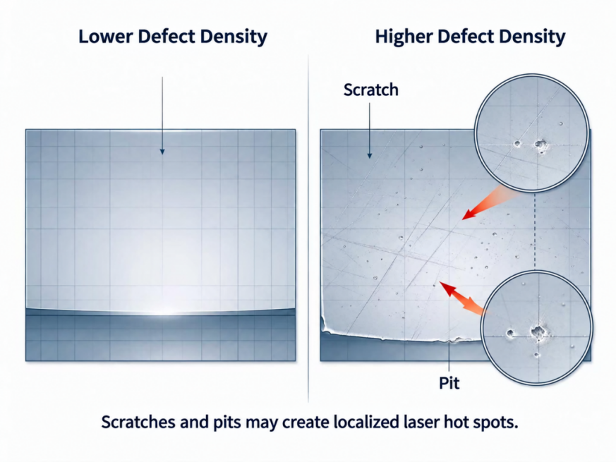
7. Surface imperfections. Scratches, pits, and contamination can cause scattering or localized absorption. Surface‑quality levels such as 20‑10 or 40‑20 may be used as project‑specific examples, but they are not universal limits for all high‑power optics. The inspection zone and clear aperture should also be specified.
8. Surface roughness. Depending on wavelength and power density, specify Ra, Rq, or an areal roughness metric together with the instrument, scan size, and spatial‑frequency bandwidth. Mid‑spatial‑frequency error and power spectral density may also be relevant for short‑wavelength or high‑power applications.
9. Surface figure and transmitted wavefront. State the test wavelength, clear aperture, mounting condition, and evaluation method. Surface‑figure error causes initial wavefront distortion; changes caused by absorption and temperature gradients during high‑power operation constitute thermal lensing or thermally induced wavefront distortion.
10. Parallelism, perpendicularity, and angular tolerances. For prisms, laser rods, and phase‑matched crystals, tolerances should be derived from beam deviation, splitting angle, or phase‑matching requirements.
11. Edge chips, bevels, and dimensions. Edge damage can act as a mechanical stress concentrator or contamination site; risk may increase if the beam approaches the edge. Bevel and edge‑chip limits should be coordinated with the clear aperture and mount design.
4 Optical Coating Inspection
12. Spectral performance. Measure transmittance, reflectance, and any required out‑of‑band response at the design wavelength, angle of incidence, and polarization. Test points such as 193, 355, 532, or 1064 nm should be selected from the actual design rather than applied to every product.
13. Absorption and scatter. Low residual reflectance does not demonstrate low absorption or low thermal load. For high‑power applications, coating absorption, scatter, and substrate residual absorption may need to be measured or controlled separately.
14. Coating uniformity. Large‑aperture or high‑precision optics may require multipoint or area mapping to assess spectral and thickness uniformity from center to edge.
15. Coating durability. Select adhesion, abrasion or wiping, humidity, water‑solubility, and thermal‑cycling tests according to the environment and customer specification. Test methods and severity levels may be based on ISO 9211. Cross‑cut adhesion and ultrasonic immersion should not be presented as universal requirements for precision optical coatings.
16. Coating stress. Changes in surface figure or wavefront before and after coating can be used to assess coating stress and its effect on component performance.
17. Short‑wavelength irradiation stability. For deep‑UV applications such as 193 or 248 nm, evaluate changes in transmission, absorption, or defect population under the actual dose, atmosphere, and exposure time.
5 Laser‑Induced Damage Threshold
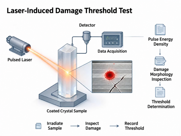
Laser‑induced damage threshold (LIDT) is an important qualification parameter for high‑power optical components, but every threshold value must be reported together with the complete test conditions. Pulsed‑laser results are commonly expressed in J/cm², while CW results may be described in W/cm² according to the applicable test method. The two cannot be compared without the relevant operating conditions.
- Laser wavelength, pulse duration, repetition rate, or CW operating mode;
- Beam size and its definition, spatial profile, angle of incidence, and polarization;
- The 1‑on‑1, S‑on‑1, R‑on‑1, or raster‑scan test method;
- Damage criterion, number of test sites, statistical method, and environmental conditions.
LIDT is generally a destructive test used for sample, lot, or design qualification and should not be described as a mandatory 100% production test. The test plan can be developed in accordance with the ISO 21254 series and the customer specification.
6 Application‑Specific Tests for Functional Crystals
Polarizing crystals and polarizers
Birefringent materials such as α‑BBO, YVO₄, calcite, and MgF₂ can be used in Glan‑type polarizers, Wollaston prisms, beam displacers, or retarders. Typical tests include extinction ratio, transmission, leakage and stray light, splitting angle, air‑gap uniformity, wavefront quality, and thermal depolarization at high power. Extinction‑ratio limits should be defined by wavelength, aperture, structure, and application rather than by a single universal “high‑power” or “lithography‑grade” value.
Nonlinear frequency‑conversion crystals
Nonlinear crystals such as LBO, β‑BBO, and CLBO can be used for harmonic generation, sum‑frequency generation, and other frequency‑conversion processes. α‑BBO is primarily used in birefringent polarizing components and should not be listed as a general‑purpose frequency‑doubling crystal. Typical tests include phase‑matching angle, angular acceptance, temperature acceptance, walk‑off angle, conversion efficiency, LIDT, and gray‑track or absorption changes after long‑term irradiation. Conversion‑efficiency data should also state pump wavelength, power, beam size, pulse duration, crystal length, and temperature‑control conditions.
Laser gain crystals
For gain media such as Nd:YAG, Yb:YAG, and Nd:YVO₄, relevant tests may include dopant concentration and uniformity, absorption coefficient or spectrum, fluorescence lifetime, emission characteristics, internal defects, stress birefringence, wavefront quality, thermal conductivity, and thermal lensing or depolarization under high‑power operation. “Saturable absorption loss” is normally associated with saturable absorbers and should not be used as a general parameter for conventional gain crystals.
7 Thermal‑Load and Operating‑Condition Validation
18. Thermally induced wavefront change. Monitor transmitted wavefront or beam quality over time at the specified power and cooling conditions to evaluate thermal lensing and thermally induced aberration.
19. Thermal depolarization. Measure extinction ratio or polarization state before and during high‑power operation to assess the effects of residual stress, absorption, and thermally induced birefringence.
20. Thermal cycling and environmental testing. The temperature range, ramp rate, dwell time, and number of cycles should reflect the operating environment, material properties, and customer specification. A range of −40 °C to 85 °C should not be applied universally.
21. Long‑term irradiation. At the specified power, dose, and operating time, record changes in transmission, extinction ratio, conversion efficiency, or wavefront, and inspect for gray tracking, coating changes, or surface damage.
22. Cooling and interface thermal resistance. For rod, slab, or thin‑disk crystals, evaluate temperature distribution, interface thermal resistance, and allowable operating power together with the heat sink, coolant, and mounting method.
8 Assembled‑Component Inspection
- Stress birefringence or wavefront change before and after assembly to identify mount‑induced stress;
- Air‑gap thickness and uniformity in cement‑free polarizing prisms;
- Seal integrity for moisture‑sensitive materials, using a method appropriate to the package design;
- Coaxiality, centration error, and alignment of flanges and mounting datums;
- Internal stray light, ghost reflections, contamination, and particles;
- Compatibility of adhesives and assembly materials with wavelength, temperature, vacuum, and laser power.
9 Inspection Reports and Procurement Acceptance Data
Delivery documentation should distinguish 100% production inspection from lot sampling and design qualification. Depending on product risk, contract requirements, and the customer specification, the package may include:
- Dimensional, angular, cosmetic, and clear‑aperture inspection records;
- Internal‑defect, refractive‑index‑homogeneity, or stress‑birefringence results;
- Optical‑axis, cut‑orientation, or phase‑matching‑angle reports;
- Surface‑imperfection, roughness, surface‑figure, or transmitted‑wavefront data;
- Transmission, reflection, or absorption data at the design wavelength;
- Functional data such as extinction ratio, splitting angle, or conversion efficiency;
- LIDT, environmental, thermal‑distortion, or long‑term irradiation qualification reports obtained under the agreed conditions.
10 Priorities for Different High‑Power Applications
- High‑peak‑power pulsed systems: prioritize LIDT, peak energy density, surface imperfections, contamination, and internal scattering defects.
- High‑power CW systems: prioritize absorption, heat removal, thermal lensing, thermal depolarization, and long‑term coating stability.
- Deep‑UV systems: in addition to surface and coating quality, consider material purity, short‑wavelength absorption, contamination control, UV irradiation stability, and protection of moisture‑sensitive materials.
Conclusion
High‑power optical components cannot be evaluated reliably using one fixed list of numerical limits. A more robust approach begins with the actual laser operating conditions, identifies the material, surface, coating, functional, and assembly risks, and then establishes the corresponding inspection and qualification plan. CX Photonics can support customers in defining appropriate inspection items and can provide standard components or custom manufacturing solutions based on wavelength, power, beam parameters, environment, and assembly requirements.
Cooperation Inquiry