How to Define and Verify Cleanliness Requirements for Prisms Used in Semiconductor Inspection
CX Photonics Technical Note
There is no single cleanliness value that applies to every prism material, wavelength, and semiconductor inspection platform. A defensible specification should define the contaminant type, particle-size or concentration threshold, inspection area, measurement method, detection limit, sampling rule, and operating environment. This technical note outlines the main factors used to establish project-specific cleanliness requirements.
1 Why Cleanliness Must Be Defined for Each Project
Prisms may be used in wafer inspection, mask inspection, automated optical inspection, spectroscopy, or deep-ultraviolet polarization systems. The effect of contamination depends on the operating wavelength, beam energy, clear aperture, substrate, coating, and assembly design. In 193 nm and other DUV systems, particles, hydrocarbons, moisture, and selected volatile contaminants can contribute to scatter, absorption, transmission loss, or long-term drift. In visible inspection systems, the dominant risks may instead be stray light, image artifacts, and localized obscuration.
For this reason, “visually clean” is not a complete acceptance criterion, and a limit used for one customer or tool should not be presented as a universal industry requirement. Cleanliness criteria should be derived from system risk, customer drawings, and verified measurement capability.
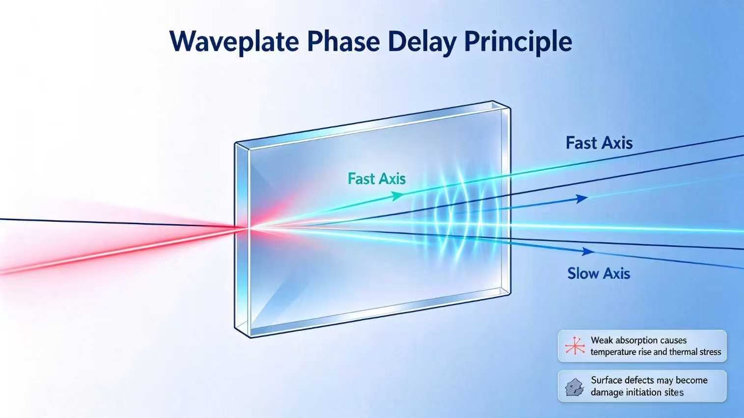
2 Four Categories That Should Be Controlled Separately
| Category | Primary risk | What the specification should define | Typical assessment approach |
|---|---|---|---|
| Surface particles | Scatter, stray light, obscuration, and secondary contamination | Size threshold, allowable count, inspection area, and statistical rule | Dark-field inspection, microscopy, surface particle measurement, or validated scatter inspection |
| Chemical residues | UV absorption, haze, contamination-film formation, and long-term drift | Chemical class, unit, sampling method, detection limit, and acceptance level | XPS, FTIR, ion chromatography, or another customer-approved method |
| Surface imperfections and texture | Scatter, wavefront degradation, and coating-reliability risk | Imperfection system, edge-chip limit, clear aperture, and roughness parameter | ISO 10110 drawing requirements, microscopy, profilometry, or AFM |
| Bulk defects | Scatter, stress, transmitted wavefront, and polarization changes | Inclusions, bubbles, striae, stress birefringence, and controlled region | Transmission, scatter, interferometric, or polarimetric inspection |
ISO 10110-7 addresses localized surface imperfections and is not a specification for removable particle contamination. ISO 14644-9 can support the assessment of surface particle cleanliness, while ISO 14644-10 addresses surface chemical contamination. These standards provide frameworks for description and assessment; they do not automatically prescribe a universal limit for a particular prism.
3 Establishing Project-Specific Requirements from Application Risk
At the start of a project, the operating wavelength, optical power or energy density, clear aperture, imaging or polarization function, substrate and coating, assembly design, and tool environment should be confirmed before cleanliness controls are selected. Internal risk categories can help communication, but they should be identified as project tools rather than ISO or SEMI classifications.
| Illustrative risk level | Typical application | Main concerns | Important qualification |
|---|---|---|---|
| High sensitivity | 193 nm DUV inspection or high-stability polarization systems | Submicron particles, hydrocarbons, moisture, coating defects, and packaging outgassing | Limits and methods must be agreed by the customer and manufacturer |
| Medium sensitivity | 248 nm, visible AOI, and precision imaging | Particles, surface imperfections, liquid residue, fibers, scatter, and stray light | Acceptance criteria should reflect the clear aperture and system resolution |
| General sensitivity | General measurement, alignment, or non-critical optical paths | Visible cleanliness, obvious particles, residue, and surface damage | Observation conditions and acceptance rules are still required |
4 Specifying Particle and Chemical Cleanliness
A particle requirement should not be written only as “dust-free” or “zero particles.” It should define the minimum particle size, counting area, controlled surface, inspection instrument, illumination and magnification, detection capability, and rejection rule. If a zero-count criterion is required, the inspected area, sample size, and statistical acceptance rule must also be stated; otherwise, an absolute zero cannot be demonstrated.
Chemical-cleanliness units must match the object being measured. Values in ng/cm² or atoms/cm² describe surface loading, whereas ppb commonly describes a concentration in air or gas. They are not interchangeable. XPS and FTIR results must also be interpreted against the method detection limit, background signal, and sampling location. Statements such as “no organic peak” should be replaced with a measurable limit and method.
Water contact angle may be used as a process-monitoring tool when the substrate and coating permit it, but it is affected by surface energy, environment, and method. It should not be the sole evidence of cleanliness. Direct water contact may also be unsuitable for hygroscopic crystals, precision coatings, bonded optics, or completed prism assemblies.
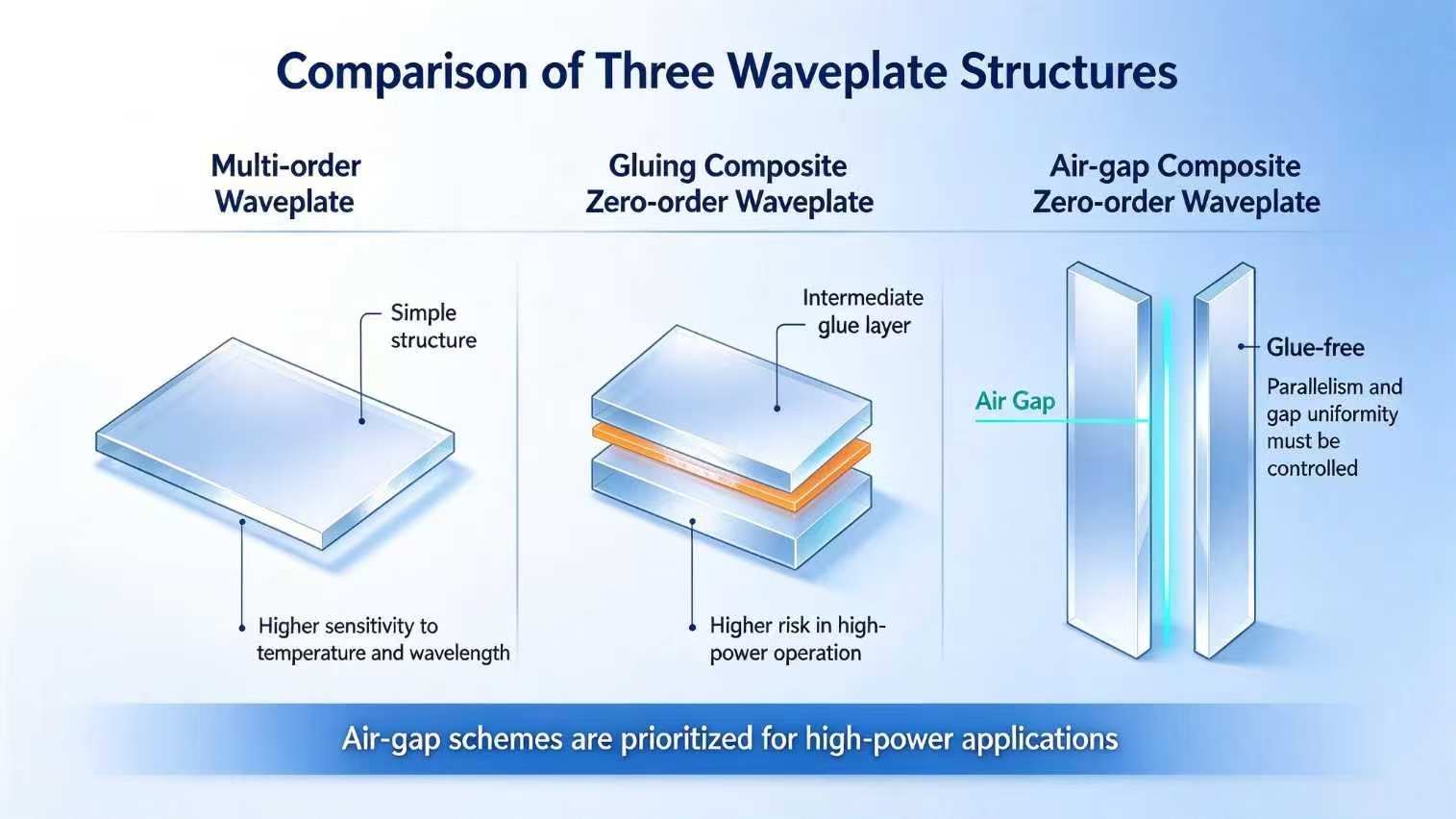
5 Surface Imperfections and Roughness Require Separate Specifications
Scratches and digs, edge chips, coating pinholes, and surface roughness are optical-quality characteristics and should not be combined with removable particle contamination. When 10/5 or 20/10 scratch-dig terminology is used, the applicable U.S. visibility-based system should be identified. When ISO 10110 is used, the drawing notation and inspection rules of that system should be followed. The two systems should not be presented as a single equivalent value without qualification.
Requirements such as Ra ≤ 0.3 nm, a specific edge-chip size, or “no pinholes” may be appropriate for a high-performance project, but the measurement area, instrument bandwidth, clear aperture, and acceptance method must be defined and justified by the system need.
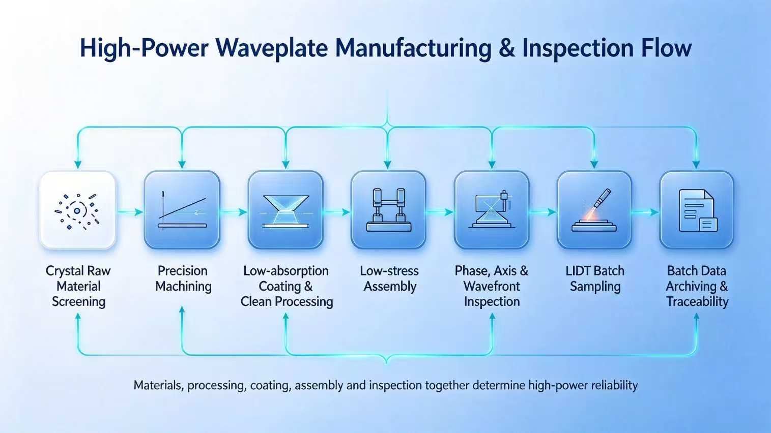
6 Cleaning Processes Must Be Validated for Material Compatibility
The cleaning process should be selected for the substrate, coating, adhesive, edge treatment, marking, air-gap design, and contamination type. Ultrapure water at 18.2 MΩ·cm, high-purity IPA, ultrasonic cleaning, and megasonic cleaning are not universal processes for all prisms. Hygroscopic or soft crystals, selected coatings, bonded parts, and air-spaced assemblies may require restrictions on liquid contact or mechanical energy.
- Begin with non-contact removal using clean, dry, oil-free, filtered low-pressure gas.
- Use only cleaning media and tools verified as compatible with the substrate, coating, and assembly materials.
- Validate ultrasonic, megasonic, immersion, bake, and plasma processes on representative samples, with defined time, temperature, power, and drying conditions.
- Complete final inspection and packaging in a controlled environment to prevent recontamination after cleaning.
7 Assembly and Packaging Require More Than a Cleanroom Class
ISO 14644-1 classifies cleanrooms and clean zones by airborne particle concentration. A room classification does not prove that the product surface has reached the same cleanliness level and does not replace product inspection. A frequent numerical error should also be avoided: for ISO Class 1, the maximum concentration at particles ≥0.1 μm is 10 particles/m³. The value 3,520 particles/m³ applies to ISO Class 5 at particles ≥0.5 μm.
Assembly and packaging controls should also address tools, fixtures, operator practices, outgassing, abrasion, gas quality, and exposure time. Air-gap dimensions, sealing method, dry-nitrogen purge, barrier bags, desiccants, and vacuum packaging should be validated for the particular product rather than prescribed for every prism.
8 Recommended Inspection and Documentation Structure
- 100% inspection: appearance, clear aperture, visible particles and liquid residue, surface imperfections, dimensions, and assembly condition.
- Lot or process qualification: surface particle measurement, chemical residue, metallic or ionic contamination, roughness, and packaging outgassing.
- Type or process validation: cleaning compatibility, coating durability, scatter, transmitted wavefront, polarization performance, and environmental stability.
- Inspection reports should record the method, instrument, detection limit, sampling location, environmental conditions, sample quantity, and acceptance basis.
Conclusion
Cleanliness for semiconductor inspection prisms is not a single number. It is a project specification aligned with application risk, measurement capability, and the manufacturing process. CX Photonics can work with customers to define cleaning, inspection, assembly, and packaging plans based on prism material, operating wavelength, coating design, assembly structure, and tool environment. All quantitative acceptance limits should be agreed before production against the customer drawing, verified process capability, and available measurement methods.
Cooperation Inquiry