How Should a High-Transmission, Low-Distortion Optical Lens Be Specified
Quick Answer
High transmission and low distortion can be pursued together, but wavelength, field of view, object distance, sensor, F-number, and allowable system loss must be defined first. Lens count, material, curvature, aspheres, coatings, and alignment jointly determine the result; single-surface reflectance must not be presented as total lens transmission.
Note: This article supports technical discussion and RFQ preparation. Manufacturable specifications, lead time, stock, warranty, and acceptance conditions are governed by the approved drawing, inspection plan, and formal contract.
Why Does This Matter to System Performance?
Lens performance is a system-level result. Material, curvature, center thickness, air spacing, coating, decenter, object distance, field of view, sensor, and wavelength jointly determine transmission, geometric distortion, wavefront, and focal quality. A single best-case value quoted without system conditions rarely represents installed performance.
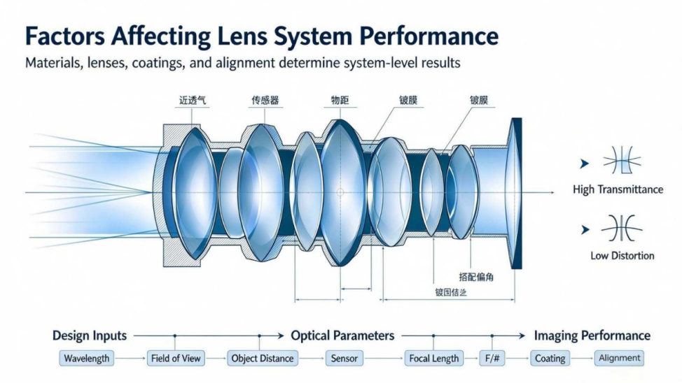
Factors Affecting Lens System Performance
Materials, lenses, coatings, and alignment determine system-level results
High Transmittance
Low Distortion
Design Inputs: Wavelength, Field of View, Object Distance, Sensor
Optical Parameters: Focal Length, F/#, Coating, Alignment
Imaging Performance
Key Parameters
| Parameter Group | Information to Confirm |
|---|---|
| System | Wavelength, FOV, object distance, sensor |
| Optical | EFL, F/#, MTF, distortion, wavefront |
| Throughput | Spectrum, surfaces, coating, test aperture |
| Mechanical | Envelope, interface, temperature, vibration |
| Acceptance | Method, field points, report |
Manufacturing and Inspection Approach
- Convert field of view, working distance, sensor, and wavelength into measurable optical requirements.
- Use optical design to balance distortion, resolution, telecentricity, throughput, size, and cost.
- Control glass batch, curvature, center thickness, decenter, surface form, surface quality, and coating.
- Measure focal length, MTF, distortion, transmission, transmitted wavefront, or spot size under the agreed configuration.
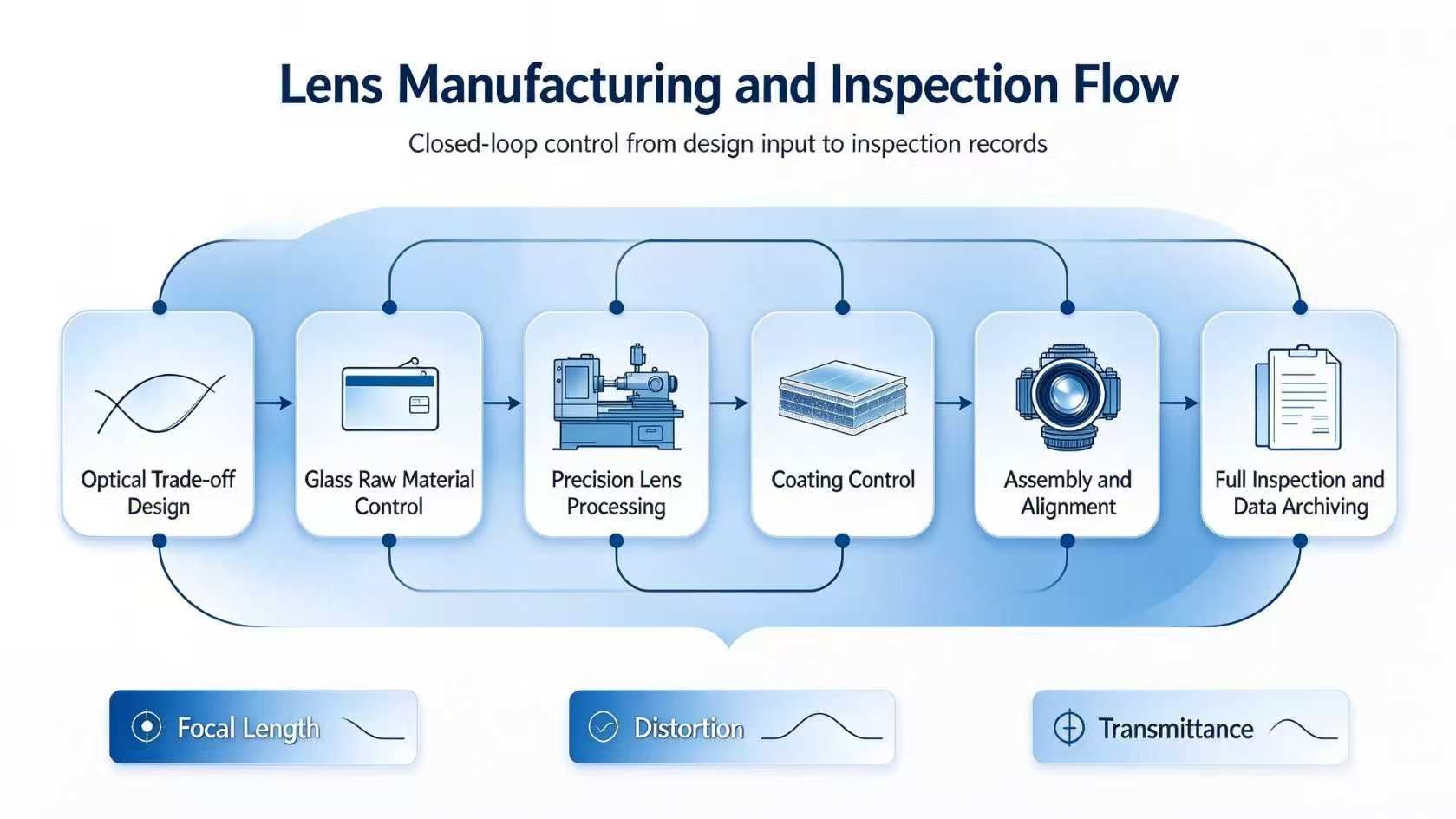
Factors Affecting Lens System Performance
Materials, lenses, coatings, and alignment determine system-level results
Common Errors and Risks
- Confusing geometric distortion with transmitted wavefront error.
- Providing only diameter and focal length without object distance, field of view, or sensor information.
- Treating single-surface reflectance as total lens transmission.
- Presenting a design target as a production guarantee without an inspection report.
Information Recommended for an RFQ
- Operating wavelength or spectrum, source type, and power.
- Object distance, image distance, field of view, sensor format, and pixel size.
- Focal length, F-number, back focal length, mechanical envelope, and interface.
- Distortion, MTF, telecentricity, transmission, or wavefront requirements and test conditions.
- Quantity, environment, prototype plan, and acceptance documents.
Frequently Asked Questions
Does an asphere automatically produce low distortion?
No. An asphere is one design tool; distortion still depends on system layout, field, object distance, sensor, and alignment.
Can system transmission be inferred from one lens surface?
No. Total transmission includes all interfaces, material absorption, coatings, scatter, and test aperture.
When is a redesign needed?
When field, object distance, sensor, wavelength, or interface changes and the existing lens cannot meet requirements.
Related Products and Capabilities
Precision Optical Components Custom Optical System Services
If your project involves a non-standard material, special wavelength, tight tolerance, or demanding environment, CX Photonics can review the drawing and application parameters before quotation and help evaluate manufacturability and the inspection plan.
Cooperation Inquiry