How Can Extinction-Ratio Instability in Glan Polarizers Be Controlled
Quick Answer
Extinction-ratio instability is rarely caused by one defect. Crystal homogeneity, axis orientation, processing stress, air gap, coating, assembly, and test alignment can all contribute. First rule out detector dynamic range and alignment errors, then investigate material, processing, and assembly using the same wavelength, aperture, and test setup.
Note: This article supports technical discussion and RFQ preparation. Manufacturable specifications, lead time, stock, warranty, and acceptance conditions are governed by the approved drawing, inspection plan, and formal contract.
Why Does This Matter to System Performance?
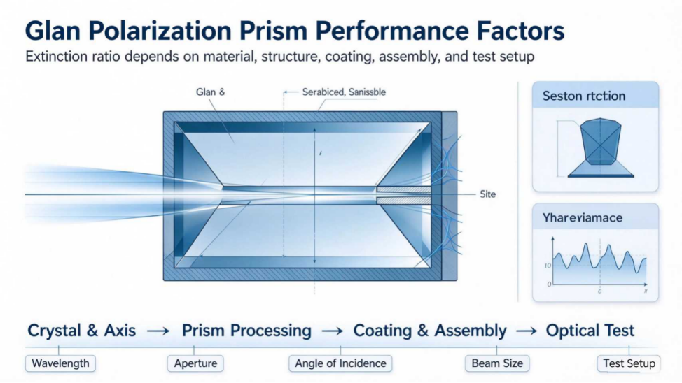
The extinction ratio, transmission, beam deviation, and laser handling of a Glan polarizer depend on crystal material, cut angle, air-spaced or cemented construction, surface quality, coating, clear aperture, mounting stress, and the test setup. Specifications should state wavelength, angle of incidence, beam size, test aperture, and measurement dynamic range.
Key Parameters
| Parameter Group | Information to Confirm |
|---|---|
| Spectrum | Wavelength, bandwidth, AOI |
| Polarization | Extinction ratio, input state, test aperture |
| Laser | CW/pulsed, power or energy, beam size |
| Construction | Material, air-spaced/cemented, housing |
| Acceptance | Transmission, deviation, wavefront, LIDT protocol |
Manufacturing and Inspection Approach
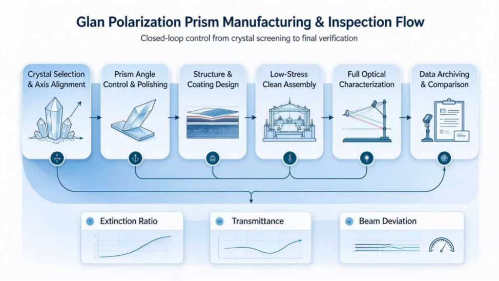
- Screen internal crystal defects and verify optical-axis orientation.
- Control prism angle, polished surface form, surface quality, and subsurface damage.
- Select air-spaced, cemented, or another construction and coating for the wavelength and laser conditions.
- Use low-stress assembly and control the air gap, housing datums, and cleanliness.
- Measure extinction ratio, transmission, beam deviation, wavefront, and appearance in the agreed setup.
Common Errors and Risks
- Guaranteeing a fixed extinction ratio or power density without test conditions.
- Treating the theoretical material transmission range as the usable range of the finished product.
- Ignoring housing stress, contamination, and air-gap variation.
- Directly comparing LIDT values measured with different pulse widths, beam sizes, or protocols.
Information Recommended for an RFQ
- Polarizer type, preferred material, and optical layout.
- Operating wavelength, bandwidth, incidence angle, and input polarization.
- CW/pulsed parameters, beam size, and power or energy.
- Clear aperture, envelope, mounting datums, and allowable beam deviation.
- Extinction ratio, transmission, wavefront, surface quality, and test method.
Frequently Asked Questions
Why can extinction ratio change with the test setup?
Detector dynamic range, stray light, angle, aperture, and alignment all affect the result.
Is an air-spaced design always suitable for high power?
It avoids an adhesive layer, but material, coating, contamination, beam profile, and thermal management still matter.
Can power-density ratings be compared directly?
Only when test conditions and damage criteria are sufficiently similar.
Related Products and Capabilities
- Polarizers - Contact CX Photonics
If your project involves a non-standard material, special wavelength, tight tolerance, or demanding environment, CX Photonics can review the drawing and application parameters before quotation and help evaluate manufacturability and the inspection plan.
Cooperation Inquiry